Slow PWM on Arduino
 I have an old Weck kettle which I occasionally use to boil my wort while brewing. The thermostat on the kettle does not allow fine control of the power input into the wort, so I decided to make a simple controller for it. I had an Arduino Uno clone lying around and it was time to put that to some use. The controller does a very slow pulse width modulation on an output pin, which (through a SSR) will control the kettle’s heating element. This control has to be very gentle so that it does not put too much strain on the AC power.
Circuit
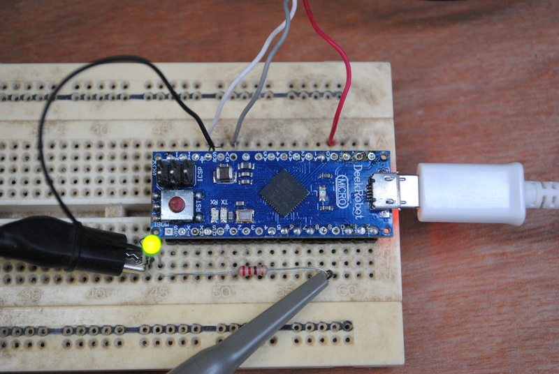
The circuit is quite simple: just a potmeter to set the duty cycle, and an output connected to a SSR to control the heater.
Potmeter
The potmeter is connected with one side to +5V, the other side to ground, and the wiper to input pin A0. This pin is connected to an analog-to-digital converter, which allows us to read the potmeters’ setting.
Output
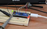
The output is connected to the input of a SSR. In this example we’ll simulate the SSR by using a LED. It is hooked up to pin 9 through a 220 Ohm series resistor to ground.
Sketch
The firmware uses a classic state machine. The state START sets the beginning of the pulse (leading edge), IN_PULSE detects when to drop the output (falling edge), and PULSE_ENDED controls the end of the pulses’ period.
First the output pin is defined. In this example we’ll be using pin 9 to hook up an LED to simulate out SSR output.
// constants won't change. Used here to set pin numbers:
const int ledPin =  9;      // the number of the LED pin
The following variable define the state machine states.
const int START = 0;
const int IN_PULSE = 1;
const int PULSE_ENDED = 2;
These variables keep track of the state machine’s state and of the set value.
// Variables will change:
int currentState = START;
int potValue = 0;
These variables are used to keep track of time. The variable period sets the period of the PWM cycle. In order not to strain the input power by switching on and off a heavy load quickly, it is advised to keep the period above 5 seconds.
// the follow variables are type long because the time, measured in milliseconds,
// will quickly become a bigger number than can be stored in an int.
long period = 5000; // pulse period (in milliseconds)
long cycleStart = 0;
The setup() routine sets the output pin to output mode, and sets up the serial console for debugging purposes.
// the setup routine runs once when you press reset:
void setup() {
	// set the digital pin as output:
	pinMode(ledPin, OUTPUT);

	// initialize serial communication at 9600 bits per second:
	Serial.begin(9600);
}
The loop() routine is where the work happens. The switch statement controls the state machine, based on the state set in the currentState variable. The code and comments should be fairly self-explanatory.
// the loop routine runs over and over again forever:
void loop() {

	switch ( currentState ) {
		case START:  // start of cycle
			cycleStart = millis();  // record time of start

			// read the input on analog pin 0:
			potValue = analogRead(A0);
	//      Serial.println(potValue);

			if ( potValue > 0 ) {
				// rising edge of pulse
				digitalWrite(ledPin, HIGH);
			} // else no need to set the pin high, duty cycle is 0%

			currentState = IN_PULSE;  //set up state machine to detect end of high state of pulse

			//send debug output to console
			Serial.println("");
			Serial.print("START, potvalue: ");
			Serial.print(potValue);
			Serial.print(", duty: ");
			Serial.print(potValue * 0.09765625); // scale back from 0-1024 to 0-100%
			Serial.print("%, cycleStart: ");
			Serial.println(cycleStart);

			break;

		case IN_PULSE:  // currently in high state, so keep track of when to end high state of pulse
			// if the set point is reached, end the high period of the PWM pulse
			if ( millis() >= cycleStart + potValue * period / 1024 ) {  // if time set by potmeter as expired, end high state

				if ( potValue < 1023 ) {
					// falling edge of pulse
					digitalWrite(ledPin, LOW);
				} // else no need to set the pin low, duty cycle is 100%

				currentState = PULSE_ENDED;  //set up state machine for detecting end of period

				Serial.print("IN_PULSE, millis: ");
				Serial.println( millis() );
			}

			break;

		case PULSE_ENDED:  //end of PWM period
			// if end of PWM period, reset for next period
			if ( millis() >= cycleStart + period ) {
				currentState = START;

				Serial.print("PULSE_ENDED, millis: ");
				Serial.println( millis() );
			}

			break;
	} // end case

} // end loop
Result
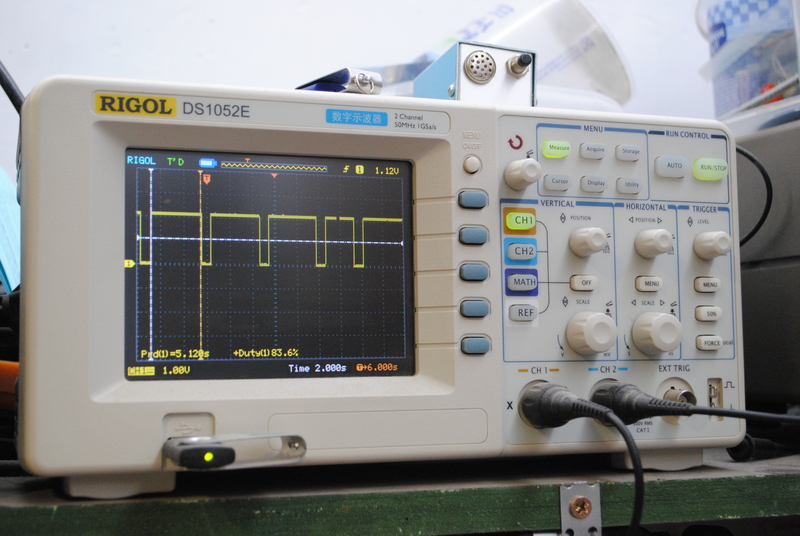
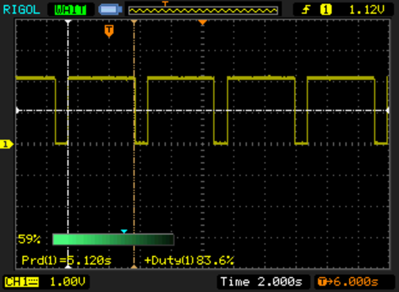
The Rigol DS1052E works a treat to display the PWM waveform on the output. Here you can see a period of roughly 5 seconds, and a duty cycle of 83.6%.
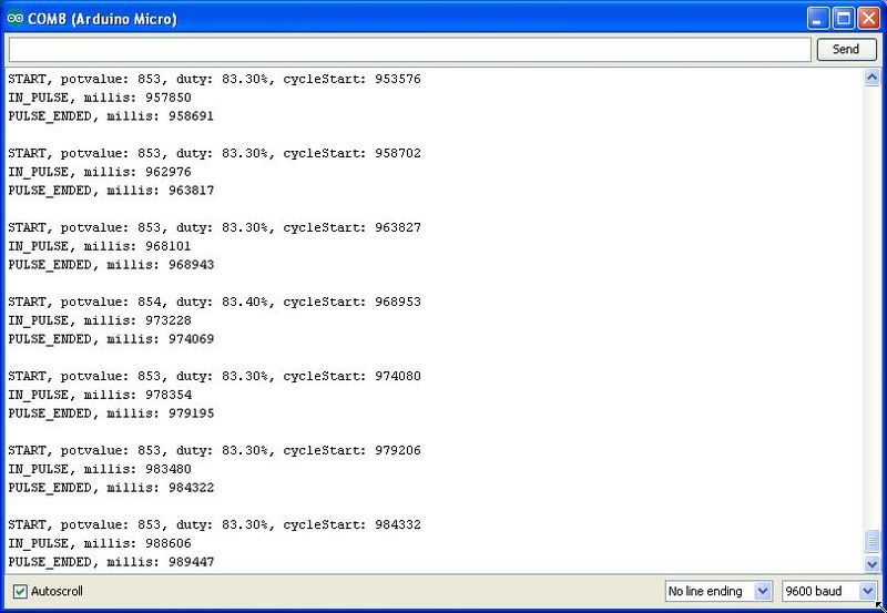
The serial console shows debugging output: